
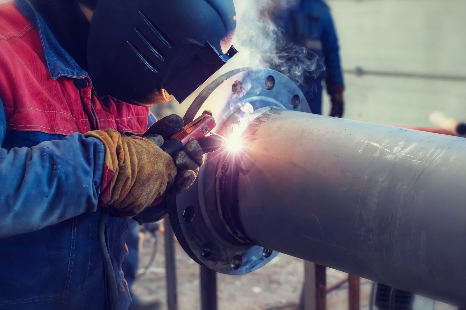
Assessment of an individual weld joint versus a leak test of the entire system
A leak test, carried out once installation is complete, checks the behaviour of the entire section of pipeline under pressure. This test detects leaks at joints, flanges or seals, but reveals little about the structure of the material within an individual weld. A weld may pass a pressure test and yet still contain internal defects that will only become apparent after months or years of operation, under the influence of material fatigue or prolonged stress.
The joint itself is tested using methods divided into two groups: destructive methods, which permanently damage or separate the specimen during the test, and non-destructive methods, which allow its condition to be assessed without interfering with its structure. The choice of technique depends on the stage of the work and on the level of assurance regarding the quality of workmanship required in a given situation.
Visual inspection as the first stage of the check
Visual inspection is a test carried out on every weld, regardless of whether further tests are planned. The principles of this inspection are set out in the PN-EN 13100-1 standard, which covers the visual inspection of joints in thermoplastic semi-finished products. In the case of a butt weld, the examination primarily focuses on the shape of the weld bead formed around the circumference of the pipe.
A correctly shaped fillet forms two closely spaced ridges, evenly distributed around the entire circumference of the joint. The difference between the maximum and minimum widths of the flange should not exceed approximately 20% of the average value, and the offset of the axes of the joined components should not exceed 10% of the pipe wall thickness. The groove between the rollers should protrude beyond the outer surface of the pipe – if it falls below it, this may indicate insufficient pressure or an incorrect temperature of the heating plate.
Visual inspection has its limitations. It allows for the detection of geometric defects and visible irregularities, but fails to identify inclusions within the weld and localised areas of insufficient fusion. Where in doubt, industry practice dictates that the outer bead should be cut off and subjected to an additional bending or torsion test.
Non-destructive testing – ultrasound and X-rays
However, visual assessment is not the only aspect covered by the PN-EN 13100 standard. It also describes radiographic testing using X-rays (Part 2), ultrasonic testing (Part 3) and high-voltage testing (Part 4), used primarily to check the insulation of the resistance wire in electrofusion fittings. All these methods allow the interior of the weld to be assessed without damaging the joint.
Radiographic testing captures an image of the inspected joint on film or in digital form, enabling the detection of cracks, pores or areas of lack of fusion within the material. The ultrasonic method involves transmitting a sound wave into the material – the wave reflects off any discontinuities and returns to the transducer, and the measurement result appears on the flaw detector’s screen.
Both methods have a longer history of use in Poland for steel joints than for polyethylene pipelines. The non-uniform structure of the material and the slight acoustic differences between the base material and the weld zone make it difficult to interpret the results unambiguously, which is why such tests are more commonly carried out in specialist laboratories and as part of post-accident analyses rather than as part of routine project acceptance procedures. However, research institutes are conducting systematic tests on the suitability of radiography and ultrasonics for plastic joints as well, which is gradually expanding the scope of their practical application.
Bending test and tensile test
The bending test is described in the PN-EN 12814-1 standard. The weld specimen is placed on two supports spaced at a specified distance apart and then loaded at a constant rate, without changing the direction of bending during the test. This method is primarily used for butt joints, whose flat, symmetrical cross-section facilitates such positioning of the specimen – electrofusion fittings, due to their more complex geometry, are usually tested using a different method, described later in this text. The result indicates whether the joint fractures within the weld or outside it – a fracture outside the weld zone usually indicates that the joint has been correctly made.
The tensile test is described in standard PN-EN 12814-2. It involves applying an axial load to the component until it breaks on a testing machine. The test determines the strength of the joint and the location of the fracture. For reduced temperatures, the variant described in Part 6 of the same standard is used, and for components with a constriction, Part 7 is used. The PN-EN 12814 series also covers the joint creep test (Part 3), which is less commonly used in routine inspection as it can take up to several dozen hours. The results of the bending and tensile tests are compared with the material manufacturer’s specifications or with the results of previous welds carried out on the same equipment.
Peel test on electrofusion joints
For electrofusion fittings, a peel test, as described in the PN-EN 12814-4 standard, is also carried out. There are several variants of this test: the T-peel test, the decohesion test and the crush test. This method makes it possible to determine the quality of the bond between the fitting and the pipe, as well as to identify areas where the plastic has not fully fused.
The interpretation of the result is based on observation of the nature of the fracture. The fracture surface should have a uniform, fibrous appearance, without any smooth, shiny areas indicating a lack of mixing of the material. The result is read immediately after the test is carried out, without the need for any additional mechanical processing or preparation of the cross-section.
Macroscopic examination of a cross-section
The macroscopic examination, as set out in the PN-EN 12814-5 standard, involves cutting a sample from the weld and inspecting the cross-section for the presence of cracks, inclusions, pores or areas of lack of fusion. This method reveals the structure of the material in areas not accessible to external visual inspection; it is therefore often carried out in conjunction with a bending or peel test, providing a complementary view of the interior of the joint.
Classification of defects in welded joints
The results of the individual tests refer to the classification set out in the PN-EN 14728 standard, which describes the types of non-conformities in welded and heat-sealed joints in thermoplastics. The standard classifies deviations such as pipe axis misalignment, irregular flash, pores or areas of lack of fusion, assigning them tolerance levels depending on the intended use of the pipeline. The results of destructive or non-destructive testing are thus compared against a specific acceptance criterion, established independently of the contractor’s experience.
When are destructive tests used in practice?
Actual welds carried out on site are rarely subjected to destructive testing, as destroying the sample means removing a section of the operational installation. Destructive testing is mainly carried out on reference samples – test welds made in parallel, using the same machine settings, the same material and under similar environmental conditions. The same procedure is used during qualification examinations for welding machine operators, as well as during the acceptance of new equipment, where a test sample replaces the inspection of an actual section of the network.
Failure of the reference sample means that the parameters must be adjusted before further work can proceed and, depending on the procedure adopted, that the welds made since the last positive result must also be re-inspected. If a weld defect is suspected, or following a failure in a pipeline in service, a section including the joint is cut out and sent to the laboratory, where a full range of tests is carried out – from macroscopic examination to tensile testing.
FAQ:
Is every weld carried out on site tested using a destructive testing method?
Welds incorporated into a completed pipeline are subjected to such tests in exceptional circumstances – when investigating the causes of a failure or as part of a spot check commissioned by the client, where an additional section of pipe is cut out before the trench is backfilled. In all other cases, the quality of the process is confirmed by the conformity of the reference sample’s parameters with the settings used for the actual welds, as recorded in the ongoing welding documentation.
How often are reference samples prepared for destructive testing?
The frequency depends on the project requirements, the client’s guidelines and the contractor’s quality procedures. In practice, reference samples are often prepared before the main work begins, as well as after any significant change in material, welding parameters or equipment, and following a change of welding machine operator. The scope of such checks is determined by the project requirements or internal quality procedures. In smaller projects, destructive testing is usually carried out less frequently, whilst visual inspection and other methods specified in the adopted procedure form the basis of the inspection.
Are ultrasound and X-ray inspections commonly used for PE pipes?
These tests are not part of routine testing, mainly due to the cost of the equipment and the time required to carry out the measurement on site, where simpler visual inspections and destructive tests provide results much more quickly. Interpreting an ultrasonic or radiographic image also requires a specialist familiar with the specific properties of plastics, as standard interpretation guidelines were originally developed for metals. For these reasons, both methods are more commonly chosen for research and analytical work than for the day-to-day acceptance of installations.
Who is authorised to carry out destructive testing of welded joints?
Destructive tests, such as bending, tensile and tear tests, are carried out by laboratories equipped with the appropriate apparatus and applying procedures in accordance with the PN-EN 12814 series of standards. These may be laboratories operating within technical inspection bodies, research institutes, certification bodies or companies carrying out materials testing. In the case of projects requiring an independent assessment, the tests are carried out by accredited laboratories specified in the documentation or designated by the client.
What does it mean if the specimen fractures outside the welded area during a bending test?
This pattern of cracking indicates that the weld withstood a greater load than the surrounding base material of the pipe, which is considered a positive result. A crack running exactly along the weld line, on the other hand, indicates a weakness at the joint, which is usually associated with an incorrect temperature, surface contamination or an insufficient heating time. The location of the specimen’s fracture is recorded in the test report as one of the quality control parameters for the manufacturing process.
